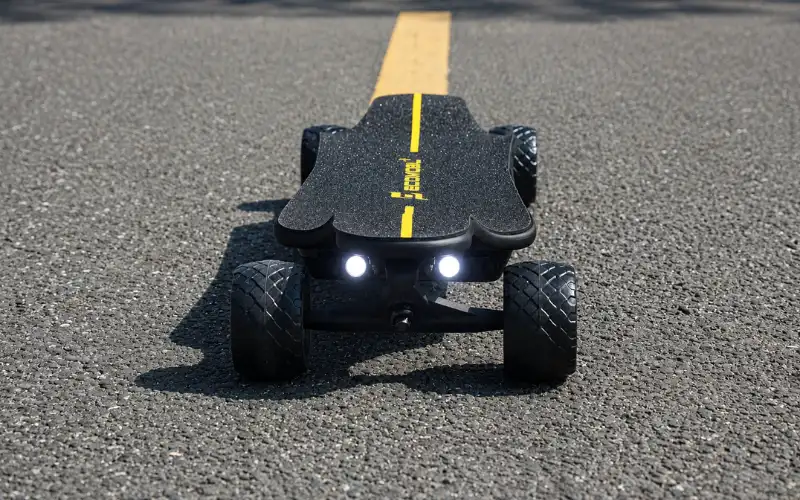


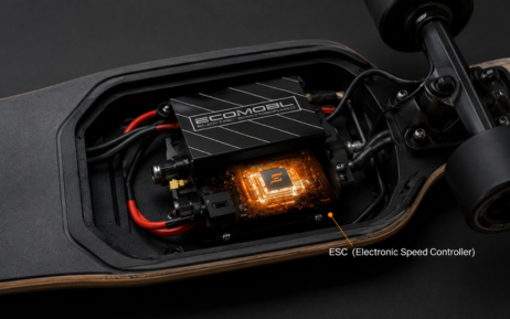
The Electronic Speed Controller is the brain behind every power surge and smooth deceleration. If you ride electric, you live and die by your ESC. Here’s everything you need to know about how it actually works.
What Is an ESC, Really?
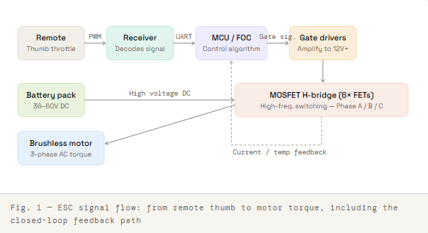
Ask most riders what an ESC does, and you’ll hear something like “it controls the speed.” That’s true, but it barely scratches the surface. The Electronic Speed Controller is the translator sitting between your battery pack and your motor. It receives a low-power signal from the remote receiver, interprets your throttle input, and then switches large currents through the motor windings in precisely timed pulses to produce smooth, controllable torque.
Without an ESC, your battery would dump raw voltage into the motor with no nuance, full speed or nothing, no braking, no smooth acceleration. The ESC is what makes an electric skateboard rideable rather than dangerous.
Key concept: An ESC doesn’t “slow down” current the way a rheostat would. It switches power on and off thousands of times per second using transistors, controlling how much energy reaches the motor over time,e not by reducing voltage directly.
Inside the ESC: The Core Components
Cracking open an ESC reveals a surprisingly compact ecosystem of components, each with a specific role in turning your thumb movement into wheel spin.
MOSFETs — The Switching Muscle
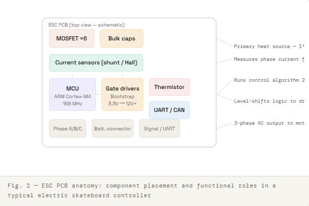
Metal-Oxide-Semiconductor Field-Effect Transistors are the workhorses of any ESC. These solid-state switches open and close at extremely high frequencies to pulse current through the motor. In a typical electric skateboard ESC, you’ll find them arranged in a three-phase bridge configuration, on six MOSFETs in total (two per phase), forming what’s called an H-bridge. The quality, ON-resistance (RDS-on), and current rating of these MOSFETs are major determinants of how much continuous and burst current your ESC can handle.
Poor MOSFET selection leads to the most common ESC failure mode: heat-related transistor death. When a MOSFET gets too hot, its resistance increases, which generates more heat a vicious thermal spiral that ends in component failure or fire.
Microcontroller — The Brain
Every modern ESC has a microcontroller (MCU) running the control algorithm. In DIY-community favorites like the VESC, this is typically an ARM Cortex-M4 processor running at 168 MHz. The MCU reads sensor data (motor position, current draw, temperature), runs the control loop, and commands the gate drivers to switch the MOSFETs accordingly, all dozens of thousands of times per second.
Gate Drivers
The MCU operates at logic-level voltages (3.3V–5V), but MOSFETs require much higher gate voltages to switch fully. Gate driver ICs bridge this gap, taking the MCU’s control signals and amplifying them to properly drive the transistors. Bootstrap gate drivers are common, using the switching voltage itself to generate the high-side drive voltage.
Current Sensors
Hall-effect or shunt-based current sensors feed real-time current data back to the MCU. This is how the ESC enforces motor current limits, battery current limits, and enables regenerative braking. Without accurate current sensing, none of the closed-loop control would be possible.
Capacitors
Large bulk electrolytic capacitors buffer the battery supply, absorbing voltage spikes that occur whenever the MOSFETs switch. Undersized or aging capacitors let those spikes reach the transistor,s another common failure vector on cheap ESCs.
FOC vs BLDC: Choosing Your Control Mode
This is the question that consumes more forum threads than almost any other ESC topic. Both modes drive brushless motors, but they do it differently, ly and the tradeoffs are real.
BLDC (Trapezoidal) Commutation
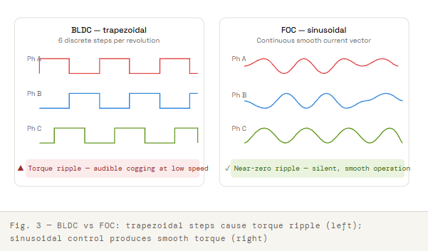
BLDC mode switches current through the motor phases in discrete steps, eps six distinct states per electrical revolution. It’s computationally simple, runs cool on the MCU, and is tolerant of noisy or imprecise motor position sensing. The downside is that each commutation step produces a small torque ripple, which at low speeds can feel notchy and at high speeds contributes to audible motor noise, or the “cogging” some riders feel at slow throttle inputs.
FOC (Field Oriented Control)
FOC (sometimes called sinusoidal commutation or vector control) is the more sophisticated approach. Rather than switching in discrete steps, FOC continuously calculates the optimal current vector to apply to the motor, controlling both the flux-producing and torque-producing components independently. The result is a smoother, quieter operation, better low-speed torque, and improved efficiency across the RPM range.
The tradeoff? FOC is computationally heavier, more sensitive to motor parameter tuning (you must accurately detect resistance, inductance, and flux linkage), and can produce higher switching losses at certain operating points, leading to more heat in the MOSFETs under specific conditions.
For most street riding and commuting, FOC wins on ride feel. For high-power racing builds where peak efficiency matters less than raw power handling, BLDC remains a viable choice.
| Feature | BLDC Mode | FOC Mode |
|---|---|---|
| Motor noise | Louder (cogging) | Near-silent |
| Low-speed smoothness | Notchy | Very smooth |
| Setup complexity | Simple | Requires motor detection |
| MCU overhead | Low | High |
| MOSFET heat | More predictable | Can spike in certain conditions |
| Best for | High-power builds | Street/commute |
Regenerative Braking: Physics You Can Exploit
When you pull the brake trigger, your ESC doesn’t activate physical brake pads. Instead, it reconfigures the motor, which is now spinning due to wheel momentum, as a generator. The motor windings, still rotating, produce a back-EMF (electromotive force). The ESC captures this and pushes current back into the battery pack.
This is genuinely useful: on long descents, regenerative braking can recover meaningful charge. But there are important constraints riders often overlook.
The Full-Battery Problem
Regen braking pushes current into the battery. If the battery is fully charged (at 100% state of charge), it cannot accept more charge;e the pack voltage will spike dangerously. Most quality ESCs detect this and reduce or eliminate regen braking force when the battery is near full, which means your brakes will feel different at the top of a hill than at the bottom of a long ride. This is not a bug; it’s a battery protection feature. Be aware of it, especially on hills.
Brake Fade at Low Speed
Regenerative braking force is proportional to motor RPM. The faster you’re going, the more braking force regen can produce. At very low speeds, regen becomes ineffective. For this reason, some ESCs blend regen with a friction braking mechanism or simply accept that near-stop braking will be reduced. Design your riding accordingly: don’t rely on regen to stop you at a crosswalk from 2 mph.
Safety note: Always test your brake feel at the start of every ride. ESC configuration, battery state, and temperature all affect braking response. Never assume brake force will be identical to your last session.
Read: How Do Electric Skateboards Actually Work? Everything You Need to Know
The ESC Parameters That Actually Matter
Modern configurable ESCs, especially the VESC ecosystem, expose dozens of tunable parameters. These are the ones that most directly affect real-world ride quality and component longevity.
Motor Current Limit
This is the maximum current the ESC will allow to flow through the motor windings. Higher values mean more torque,e useful for hills and acceleration. But sustained high motor current means high heat in the motor and ESC. Set this based on what your motor is rated for (check the datasheet), not just how fast you want to go.
Battery Current Limit
A separate limit from motor current, not this is the maximum current the ESC will draw from the battery. This should not exceed your battery’s continuous discharge rating (in amps). Exceeding this damages cells and shortens the pack’s life significantly. Many riders set the motor current high for performance and the battery current conservatively for longevity.
Absolute Maximum Current
A hard cutoff that triggers immediate motor shutdown if the instantaneous current exceeds this value. Set this higher than your motor limit (around 130–150% of it) to prevent nuisance cutoffs on big hits, but low enough to protect your hardware in a genuine fault condition.
ERPM Limits
Electrical RPM limits cap your top speed. ERPM equals mechanical RPM multiplied by the number of motor pole pairs. Setting appropriate limits protects both the motor and the ESC from over-speed conditions important if you’re using a high-kV motor on a high-voltage pack.
Duty Cycle Current Limit Start
Often overlooked, this parameter reduces current limits as the motor approaches maximum duty cycle (near top speed). Without it, the ESC tries to push high current into a motor that’s already at near-full voltage, a recipe for MOSFET destruction at speed. Set this to around 85–90% of maximum duty cycle.
Ramp Times
Acceleration and braking ramp rates control how quickly the ESC responds to throttle/brake inputs. Faster ramps = more aggressive response. Slower ramps = smoother, gentler feel and less mechanical stress on the drivetrain. For beginners, slow ramps also significantly reduce the chance of a speed wobble or balance incident.
Single ESC vs Dual ESC Configurations
Most production electric skateboards use a single ESC to control one motor (single-drive) or are architected with a dual ESC, one controller per motor for dual-drive setups. The DIY world has more options.
Single ESC, Single Motor
Simple, reliable, easy to tune. Limited to one motor’s worth of torque and one motor’s worth of failure modes. Most appropriate for lighter riders, flat terrain, and boards prioritizing range over power.
Dual ESC (Two Controllers)
Each motor gets its own ESC. This doubles your component count (and failure chances) but allows independent motor control useful for torque vectoring in theory, though most esk8 applications don’t exploit this. Communication between the two controllers via CAN bus is essential to keep them synchronized; otherwise, they’ll fight each other and produce unpredictable braking behavior.
Dual-Channel Single ESC
Some ESCs integrate two independent motor controller channels into one board, such as the VESC 6 MK, VI, and several production-board units do this. This is architecturally more elegant than two separate controllers and simplifies thermal management into a single design. The downside is that a single fault can kill both channels simultaneously.
| Configuration | Motors | Complexity | Redundancy | Best Use |
|---|---|---|---|---|
| Single ESC + Single Motor | 1 | Low | None | Commuting, light use |
| Two ESCs + Two Motors | 2 | High | Partial | Performance / DIY |
| Dual-channel ESC + Two Motors | 2 | Medium | Low | Production boards |
Heat: Your ESC’s Biggest Enemy
Heat kills ESCs. This is not hyperbole; the majority of ESC failures in electric skateboards can be traced back to thermal issues. Understanding where heat comes from and how to manage it is essential for building a reliable setup.
Sources of ESC Heat
Every switching event in the MOSFETs generates a small amount of heat (switching losses). At a 20–30 kHz switching frequency, these add up fast. Conduction losses (I²R heating as current flows through the MOSFET’s resistance) compound this effect. In enclosed board enclosures with poor airflow, heat accumulates rapidly, especially on long, steep hills where both current and time are high.
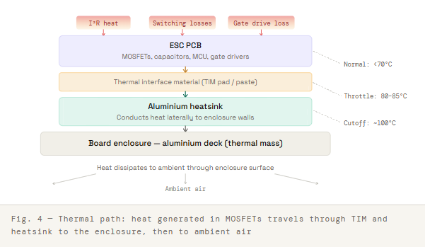
Thermal Throttling and Cutoffs
Quality ESCs monitor temperature via an on-board thermistor and begin reducing current limits as temperatures rise,e called thermal throttling. If the temperature continues climbing past a threshold (typically 85–100°C depending on hardware), the ESC may cut power entirely. This is a self-protection feature, not a flaw, but experiencing a power cutout mid-hill at speed is genuinely dangerous. Knowing your ESC’s thermal behavior before a demanding ride is non-negotiable.
Improving Thermal Performance
The standard approaches: ensure good thermal interface material between the ESC PCB and its heatsink, mount the heatsink to the enclosure base so the board itself acts as a thermal mass, and wherever the enclosure design allows, provide airflow paths. Some advanced DIY builders add small fans or use phase-change materials in their enclosures. At a minimum, never leave your ESC mounted in dead air with no heat path.
How the Remote Talks to the ESC
The remote receiver sends throttle and brake position data to the ESC. There are three protocols commonly used in electric skateboarding, and the differences matter.
PWM (Pulse Width Modulation)
The oldest protocol is a simple analog signal where pulse width represents throttle position (typically 1ms = full reverse/brake, 1.5ms = neutral, 2ms = full throttle). PWM is universal but carries no error checking. If signal pulses are missed or corrupted, the ESC has no way of knowing whether it maintains the last known position, triggers a failsafe, or, in the worst case, responds erratically. For safety-critical applications, PWM’s lack of error correction is a serious concern.
UART (Serial Communication)
A digital serial protocol that can carry much richer data, not just throttle position, but battery telemetry, motor temperature, fault codes, and more. UART allows bidirectional communication, meaning the remote can display real-time data from the ESC. Error detection is built in. This is the protocol used by most quality aftermarket remote systems today.
CAN Bus
Originally developed for automotive applications, CAN bus is a robust differential signaling protocol designed for electrically noisy environments. In electric skateboarding, CAN is primarily used for ESC-to-ESC communication in the dual-motor setup, allowing two controllers to synchronize motor current and braking force in real time. CAN is significantly more noise-immune than UART, which matters when you’re running high-current motor cables alongside signal wires.
The VESC Ecosystem
No discussion of electric skateboard ESCs would be complete without addressing V, C, the open-source motor controller platform originally developed by Benjamin Vedder. The VESC project has become the de facto standard for serious DIY electric skateboard builds, and its influence has spread into commercial products as well.
What makes VESC significant is the combination of open firmware, a capable PC/mobile configuration tool (VESC Tool), and a hardware reference design that has spawned dozens of derivative products from manufacturers worldwide. The firmware supports both FOC and BLDC modes, full parameter configurability, real-time telemetry, and a plugin system for custom applications.
The trade-off is complexity. VESC setup is not plug-and-play. Motor detection must be run for FOC mode, current limits must be set to match your specific hardware, and misconfiguration can destroy motors or batteries. The learning curve is steep, but the ceiling is. Experienced builders use VESC to unlock performance that no closed-system commercial ESC approaches can match.
Builder tip: When configuring a VESC-based system, always run motor detection with the motor unloaded (wheels off the ground) and double-check battery current limits before your first ride. Setting motor current to 80A when your battery is only rated for 30A continuous is a fast way to ruin an expensive pack.
Choosing an ESC: What to Actually Look For
The spec sheet for any ESC will feature impressive-looking numbers. Here’s how to read them critically.
Continuous vs Peak Current Rating
A “100A ESC” rated for 100A peak might be rated for only 30–50A continuous. Peak ratings are typically achievable only for a few seconds before thermal limits kick in. Always evaluate the continuous current rating against your use. Sustained hill climbing at 20+ mph draws sustained current, not peak.
Voltage Rating
Ensure the ESC’s voltage rating exceeds your fully-charged pack voltage with meaningful headroom. A 12S lithium pack charges to ~50.4V. An ESC rated to 50V is operating at its absolute limit from the moment you plug in a full pack. Seek ratings of at least 15–20% above your full-charge voltage.
Firmware Accessibility
Closed-firmware ESCs limit your tuning options and leave you dependent on the manufacturer for updates and bug fixes. Openfirmwares, areas, or at minimum, well-documented configuration interfaces give you control over the ride experience and longevity of the product.
Thermal Design
Look at how the ESC manages heat. Is there an integrated heatsink? What are the thermal cutoff temperatures? Does it support a temperature sensor output? These details aren’t always prominently advertised, but make a significant difference in real-world reliability.
Support and Community
For DIY builds, especially, an active community around your ESC platform is an underrated feature. When something goes wrong (and something will), access to experienced users who’ve solved the same problem is worth more than a slightly higher spec sheet.
Common ESC Failures and How to Prevent Them
MOSFET Failure
Usually caused by: exceeding current limits, overheating, voltage spikes from undersized capacitors, or motor phase shorts. Prevention: set conservative current limits, ensure good thermal management, use quality capacitors, and inspect motor cables regularly for chafed insulation.
Capacitor Failure
Electrolytic capacitors degrade over time and with heat. Symptoms include increased voltage spikes and erratic ESC behavior. On DIY builds, capacitors can be replaced; it’s one of the higher-ROI upgrades on older hardware.
Firmware / Configuration Issues
Not a hardware failure, but responsible for many “failed ESC” diagnoses. Before concluding that an ESC is dead, verify: has the firmware been corrupted? Has a configuration parameter been set out of range? Has the receiver’s failsafe been triggered? Many ESCs have survived what looked like catastrophic failure with a firmware reflash and clean configuration.
Water Ingress
Electric skateboards and moisture are in a persistent conflict. Water reaching the ESC PCB causes shorts, corrosion, and component damage. Conformal coating on the PCB (a thin protective layer applied to the board) is a simple and highly effective mitigation that many quality ESCs ship with it, and it can be applied after-market with a spray can.